A BOM description such as “4.7 µH, 10 A” leaves a purchasing team with an important unanswered question: what does the current figure measure? It might describe an inductance drop under DC bias, a specified temperature rise, or another manufacturer-defined limit.
For power inductors, the saturation current and heating current answer different questions. Reading both helps OEM and contract-manufacturing teams avoid approving a component that looks adequate in a catalog but lacks the required magnetic or thermal performance. Start by turning the single inductor current rating into two separate checks.
Isat vs Irms: two checks that cannot replace each other
Saturation current, usually written Isat, identifies the current at which inductance has decreased by a stated percentage from its low-current reference value. Heating current, often labeled Irms, identifies a current associated with a stated temperature rise under the manufacturer's test conditions. Coilcraft explains these definitions in its current and temperature ratings guidance.
The distinction affects which application value you compare. Peak inductor current matters for magnetic behavior. RMS current matters for resistive heating. Neither figure alone establishes suitability for the whole converter.
| Published parameter | Question it helps answer | Condition to record |
|---|---|---|
| Isat or saturation current | How much inductance is retained at the expected peak current? | Percentage drop, reference measurement, temperature, and whether the value is typical or guaranteed |
| Irms or heat-rating current | What self-heating is associated with the applied current? | Temperature-rise criterion, ambient temperature, mounting conditions, and measurement method |
| DCR | How much winding resistance contributes to loss? | Typical or maximum resistance and its specified temperature |
Keep those conditions beside the numbers in a comparison sheet. A larger amperage value becomes meaningful only after its definition is clear.
A real 4.7 µH example: what the 10 A figure leaves out
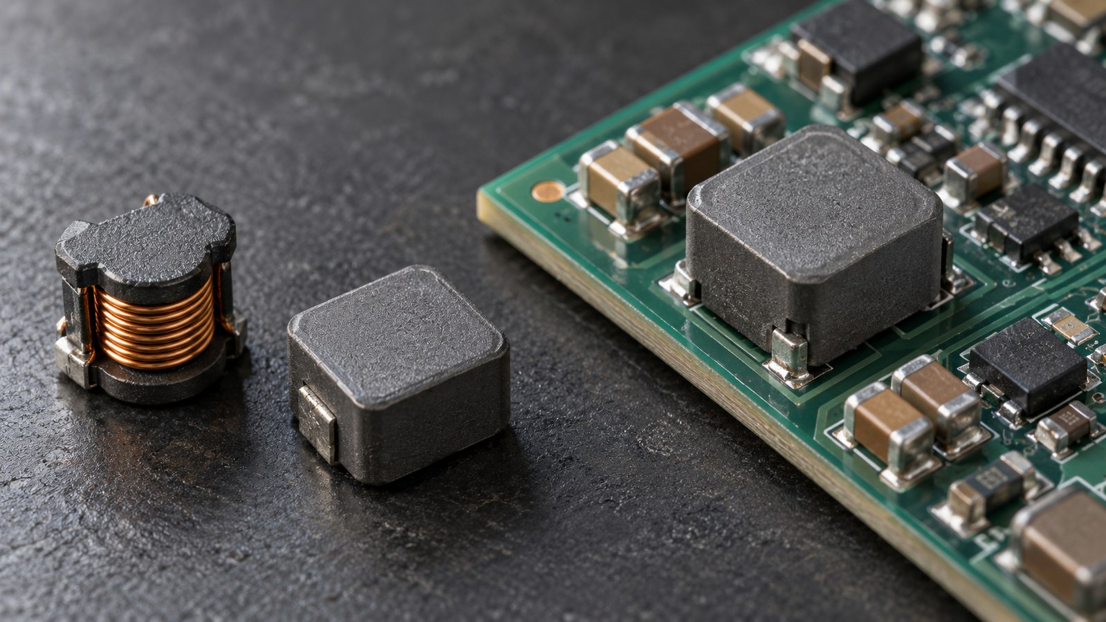
The Cplus catalog includes the Vishay IHLP2525CZER4R7M01 power inductor. Its short description includes 4.7 µH and 10 A. The manufacturer's IHLP-2525CZ-01 datasheet, document 34104, revision 01-Oct-2026, supplies the context:
- Nominal inductance: 4.7 µH, with ±20% tolerance under the specified measurement conditions.
- Typical heat-rating current: 5.5 A, defined by an approximately 40°C temperature rise.
- Typical saturation current: 10 A, defined by an approximately 20% inductance decrease.
- DCR at 25°C: 37 mΩ typical and 40 mΩ maximum.
These figures appear together in the Vishay electrical table and rating notes. The same document identifies ER as a tape-and-reel packaging code. Preserve the complete ordering number when requesting material.
The 10 A figure therefore does not establish a 10 A continuous thermal capability. Conversely, 5.5 A is a defined heating reference, not automatic permission to operate at that current in every enclosure. Both currents are listed as typical. Engineering must assess the intended operating conditions and any required production limits.
This is a rating-reading example, not a substitute recommendation or confirmation of stock. The useful purchasing improvement is to retain both current definitions instead of copying one amperage figure into the internal item description.
Calculate the current the inductor actually carries
Ask engineering for the inductor waveform rather than using the power supply's output-current label alone. For an ideal buck converter in continuous conduction with triangular ripple, peak current equals average inductor current plus half the peak-to-peak ripple. RMS current includes both the DC component and that ripple. Microchip presents these relationships in its inductor-selection equations.
Hypothetical calculation: assume a buck stage carries 4.0 A average inductor current with 2.0 A peak-to-peak triangular ripple:
- Peak current = 4.0 + 2.0 / 2 = 5.0 A.
- RMS current = √(4.0² + 2.0² / 12) ≈ 4.04 A.
The magnetic screen uses the 5.0 A peak; the initial heating screen uses approximately 4.04 A. These are illustrative waveform calculations, not measured results for the Vishay component. They do not establish its temperature or approve it for this hypothetical circuit.
Do not transfer the buck example unchanged to a boost, flyback, discontinuous-conduction, or pulse-skipping operating mode. Have engineering provide the appropriate current calculation or measurement for the actual topology and mode.
The review also needs operating extremes. Ask what happens at input-voltage limits, startup, load steps, and the controller's current limit, including relevant tolerances. Microchip's MCP16367/8/9 selection guidance specifically calls for saturation margin and consideration of overcurrent conditions. Use the requirements of your own controller rather than adopting another device's recommended inductance or margin.
Make competing ratings comparable before ranking parts
Two suppliers can publish different Isat values because they use different allowable inductance reductions. A current quoted at a 30% drop cannot be ranked directly against one quoted at a 10% drop. Request inductance-versus-current curves and compare the inductance retained at your required current.
Curve shape matters too. Ferrite and composite constructions can have different saturation behavior. Monolithic Power Systems discusses both the rating criterion and the shape of the decline in its power-inductor parameter guide. A gradual decline still needs to stay within the converter's acceptable inductance range.
Apply the same discipline to thermal figures: list the temperature-rise criterion and test environment for each candidate. A higher current quoted with a larger permitted rise does not, by itself, demonstrate a cooler component.
Use three comparison outcomes: requirements supported, requirements not met, or information missing. The third outcome is useful. It tells procurement exactly what evidence to request instead of allowing an incomplete specification to become an assumed pass.
Reserve a separate decision for the installed temperature
A DC heating rating does not capture every switching loss. Coilcraft's introduction to inductor specifications explains that operating frequency, current, and temperature affect loss, and that manufacturer analysis tools can account for core and winding effects.
Ask for loss estimates at the intended frequency and ripple conditions, then verify the component on the actual board. Include nearby heat sources, enclosure airflow, copper layout, and the hottest required operating condition. Check both the allowed component temperature and the converter's electrical behavior.
For the Vishay example, the linked datasheet specifies that part temperature, including ambient and self-heating, must not exceed 125°C under worst-case operation. That limit belongs to this documented series; it is not a universal limit for all inductors.
Give purchasing a requirement it can quote accurately
The final handoff can be a short attachment to the BOM line:
- Identify the complete approved manufacturer part number and the board revision where it is used.
- State the required inductance range, including the acceptable value under operating bias.
- Record peak and RMS current requirements, waveform assumptions, and relevant transient conditions.
- Attach saturation and heating criteria, temperature limits, DCR requirements, and supporting document revisions.
- Specify physical fit, height, land pattern, packing format, and applicable qualification requirements.
- State whether alternatives are prohibited, already approved, or being requested for engineering evaluation.
The broader electronic component sourcing guide covers supplier, documentation, and commercial checks. Keep those alongside this electrical review so neither gets lost during an urgent purchase.
Cplus Electronics lists inductors among its component sourcing categories. When you submit an inductor sourcing requirement, include the approved part, quantity, delivery requirement, and the technical attachment if candidates are needed. The supplier can then respond to a defined requirement, while engineering retains responsibility for application approval.