A TVS diode described as “24 V” does not hold a protected circuit at 24 V during a surge. That number commonly identifies its reverse standoff voltage. The clamping voltage can be considerably higher, and it is specified at a particular current and pulse condition.
This distinction matters when engineering selects protection for a new board or purchasing receives a proposed alternate. TVS diode selection needs to answer two questions together: will the device stay within its normal operating limits, and will it limit a defined transient sufficiently to protect the downstream circuit?
A voltage and wattage in a catalog description cannot answer both questions. Read them as entry points into the manufacturer's data, then keep the selection conditions attached to the approved BOM line.
Three TVS voltage ratings describe different conditions
Manufacturers may use slightly different symbols, so read the definitions in the relevant datasheet. The following distinctions are central to Analog Devices' TVS selection guidance.
| Rating | What it describes | What to check |
|---|---|---|
| Reverse standoff voltage, VRWM or VWM | The working-voltage limit associated with the specified leakage behavior. | The highest normal voltage across the device, including supply tolerance. |
| Breakdown voltage, VBR | The voltage measured at a specified breakdown test current. | The minimum and maximum values, test current, and temperature conditions. |
| Clamping voltage, VC or VCL | The voltage specified during a defined pulse at a stated peak current. | The relevant surge current and waveform, followed by the protected circuit's voltage limits. |
Breakdown voltage is not the final surge voltage seen by the load. Similarly, a clamping figure without its current condition is incomplete. When comparing two datasheets, place the test conditions beside the numbers rather than comparing the voltage columns alone.
A real 24 V example shows the difference
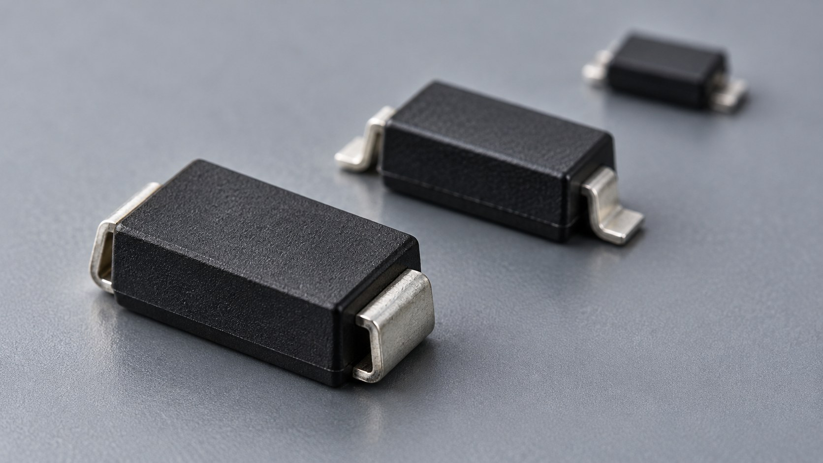
The MASMCG24CAE3 TVS diode provides a useful example. Its manufacturer's family electrical table lists 24 V standoff, a 26.7–29.5 V breakdown range at 1 mA, and 38.9 V maximum clamping at 38.6 A. The table is specified at 25°C unless otherwise stated, and its pulse-current condition follows the 10/1000 µs waveform.
These values come from the manufacturer-authored RF01001 revision A family datasheet. They illustrate three different operating points, not three interchangeable descriptions of a 24 V clamp. Obtain the applicable current documentation for an actual design release.
Nor is 38.9 V a prediction for every surge current, pulse shape, temperature, or board layout. Use the manufacturer's appropriate curves, limits, and application support to assess the conditions your circuit must withstand.
Define the voltage window before choosing a rating
Start with the maximum normal voltage across the proposed TVS, not simply the nominal rail name. Separately, identify the voltage the protected IC or other component is allowed to experience. Use any applicable transient limits and durations in its documentation; an absolute maximum rating is a boundary, not a preferred design target.
Hypothetical screening example: Assume a nominal 24 V supply can reach 28.8 V during permitted operation. A candidate with a 24 V standoff rating does not cover that stated normal range. Selecting a higher-standoff device addresses that first screen, but its clamping behavior must still fit the downstream device's limits.
If a candidate's documented clamping level at the relevant surge current exceeds the permitted voltage, its breakdown rating does not rescue the selection. Ask engineering to review the protection architecture if no suitable operating window exists. Do not resolve the mismatch by choosing whichever voltage appears closest to “24 V.”
For power-input circuits, also distinguish a short transient from a sustained abnormal supply voltage. These are different design cases and should have separate acceptance criteria.
Read pulse power together with waveform and temperature
A peak pulse power rating is conditional. “1500 W” does not describe continuous dissipation, and it cannot be compared meaningfully with another power figure until the pulse conditions are known. A 10/1000 µs rating and an 8/20 µs rating describe different current waveforms.
ROHM's TVS selection application note distinguishes pulse-current and pulse-power requirements and identifies their waveform conditions. Ask engineering to record the expected event, source impedance, current reaching the protection device, and required repetition conditions.
Use this comparison rule: keep the current, waveform, temperature, and clamping conditions together. Check the applicable temperature derating curve and repetition restrictions. If a datasheet lacks the information needed for the required event, request manufacturer clarification rather than converting between waveforms by assumption.
A component's published ESD withstand rating also should not become an unsupported claim that the assembled product passes a surge or immunity test. Keep component ratings and system validation results as separate records.
Polarity, leakage, and capacitance can change the decision
Unidirectional and bidirectional TVS devices have different current-voltage behavior. A unidirectional device can clamp a negative excursion through forward conduction; a bidirectional device behaves differently. Select for the actual signal swing and protection circuit rather than treating “bidirectional” as an automatic upgrade.
Toshiba's selection guidance highlights signal polarity and capacitance as well as voltage. A signal that legitimately crosses ground needs a suitable protection arrangement, and a high-speed interface needs a capacitance assessment. A power-rail protection device should not be transferred to a data line solely because the working voltages appear similar.
Check leakage against the circuit's requirements too. For a battery-powered node or sensitive analog input, include an explicit allowable leakage or error budget in the review. Ask for the relevant voltage and temperature conditions, not just a typical room-temperature figure.
Check the package drawing, not just “SMC”
Physical shorthand can conceal a meaningful difference. The manufacturer distinguishes the SMCG gull-wing design in DO-215AB from the SMCJ J-bend design in DO-214AB. The MASMCJ30CAE3 listing is an example of the latter family, while the earlier MASMCG24CAE3 example uses the gull-wing family.
These examples have different voltage identifiers as well as package styles; they are not proposed substitutes. Match the exact mechanical drawing, land pattern, height, polarity or orientation requirements, and assembly constraints before approving a purchase. Neither a product listing nor this comparison establishes current stock, delivery timing, or application suitability.
Keep a short selection record with the BOM
A useful approval record should let another engineer reconstruct why the device was selected. Include:
- The exact manufacturer and complete orderable part number.
- The protected node, normal voltage range, and downstream voltage limits.
- The expected transient or required test, including waveform and source conditions.
- The applicable clamping-current data, pulse capability, temperature limits, and unresolved questions.
- Polarity, leakage, capacitance, package drawing, and assembly checks.
- The validation plan, result, approval owner, and affected board revision.
Keep board-level verification in that plan. Texas Instruments' transient-protection guidance explains that layout affects protection performance and recommends a low-impedance ground connection and placement near the exposed connector for ESD protection. A suitable component on paper still needs evaluation in the intended implementation.
Purchasing can then request the approved device or clearly identify a proposal that requires engineering review. For supplier and documentation checks beyond the electrical selection, use the existing electronic component sourcing guide.
When sending Cplus Electronics a component sourcing request, include the exact part number, quantity, delivery requirement, and whether alternates are permitted. If engineering is still evaluating candidates, attach the selection criteria and keep approval pending until the required evidence is complete. That makes a supplier response useful without mistaking a matching catalog description for a validated protection design.